You might be surprised to know that most of the 3D has already been done for you but let’s have a look at what else we can do to make the board look more realistic. If you don’t have a 3D work sheet available, right click anywhere in the PCB work sheet and select `view in 3D’. Have the properties panel open and pinned into place and make sure you have the 3D key tab selected which enables these tool bar items (I have split them so they can be seen more clearly).
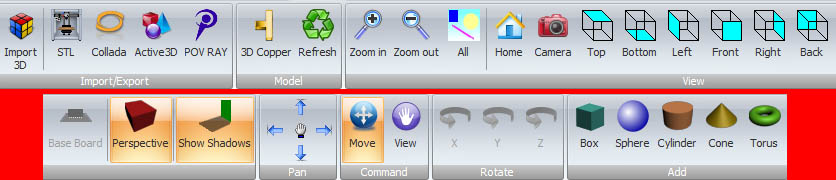
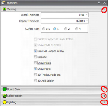
Have a bit of a play with the various view options, Home, Camera, Top, Bottom etc. then click on the VIEW (with the hand in the middle) and you can now rotate your board in real time in all angles and directions so you can have a good look at your layout. Experiment with perspective on/off and shadows on/off then we will look at the properties panel and we can see the following options. I have marked the expand/contract chevrons that open/close more options. Experiment with these options but I suggest selecting:
Show Holes
Show Parts
3D Tracks, Pads etc.
Add Solder
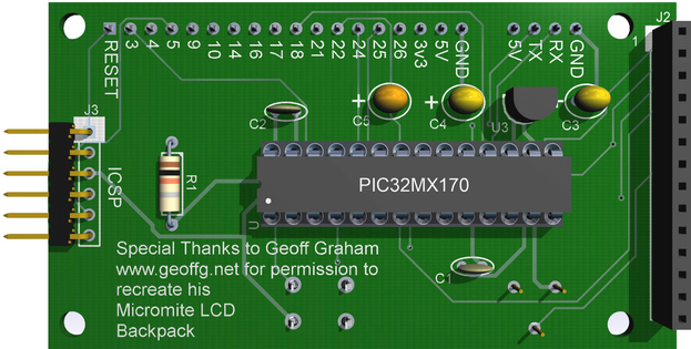
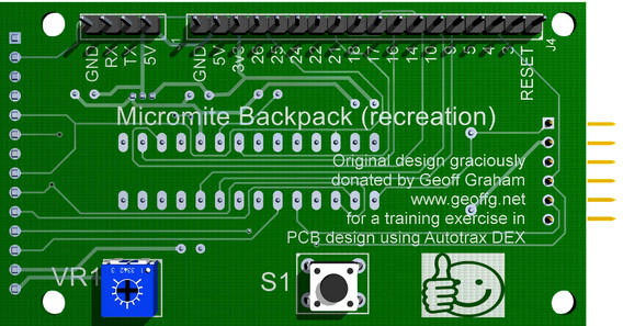
Already the board is starting to look pretty good, now you can contract the viewing options by clicking the chevrons and expand the Board colour (Hmm, US spelling used on a British product). I won’t add a picture for this as it is pretty self-explanatory and by now you are nearly an expert. But select a colour for your PCB by any of the means offered, I prefer to use the swatch, I selected dark green. Under the colour selection you will see a check box for `textured PCB’ this puts the fiberglass weave onto the board, the slider below that is the strength of that weave, I selected the textured PCB and used about 50% strength. Looking better now? Thought you would think so.
Now, contract the Board colour and expand the solder resist options. Once again chose the solder resist colour (I chose dark green again and using the transparency bar below the colour selection box I chose 0.500 (50%), Wow! Now look at your board. There is one more effect to look at and that is lighting, contract the Solder resist settings and expand the lighting settings. You can change the direction of the lighting and the intensity I left the defaults except I changed intensity to about 2/3. Your board is looking pretty cool now I bet.
Now, as good as the board is now looking, no one would really solder their PICMX170 directly to the board would they? Let’s add an IC socket shall we?
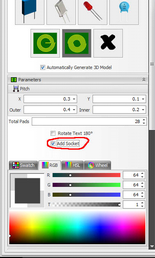
Close the properties panel and open the part builder panel.
Right click in the 3D screen and select PICK.
Click on the PICMX170 (see it highlight?), being careful not to move it from its position (remember Un-Do or Ctrl-Z if you do move it accidentally), then in the parts builder panel scroll down to just above the colour selection area place a tick in the Add Socket check box. And what do you know? A socket appears!
Congratulations! Your board design is now finished!
That concludes Part 6, “3D”
That completes “How to design and build a PCB using AutoTRAX DEX”
What Now? Hmm.. Let’s have a bit of fun!
Make sure your board is safely stored away and backed up so we don’t permanently destroy any of our hard work.
Go into the 3D view and position the 3D image to view from the BACK and (with View clicked, `the hand icon’ ) drag the board down a little to see the disc ceramic capacitor.
Right click in the 3D work sheet and select PICK, click on that capacitor and open the part builder panel.

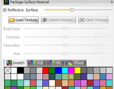
Scroll down in the part builder till just above the colour selection you find the `Load texture’ button. Click this and navigate to a suitable image file that you want to place on that part.
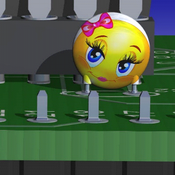
I chose a cute smiley face I found on the internet! You should now see this image on the capacitor. Not bad..
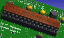
Want a wooden IC?
I found an image of some wood and applied
That to the IC and got an interesting result.
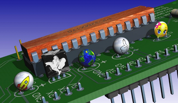
What about Marilyn on a Voltage Regulator? Or a map of the world? Or a rocket or a big thumbs up? What do you want to add? Of course textures can be used to great effect to enhance a 3D model (make it look more plastic or rough and grainy) which is of course the main reason for this feature. You need to play with it and see what YOU can do with it.
I think this is enough for this document. I hope you have enjoyed the trip into how I design boards using AutoTRAX DEX. The main thing is to play and experiment with it and see what the various options and features do. Don’t forget the huge range of video clips available to show how to do various steps and of course there is the manual to download that currently has 760 pages to read before bedtime. I am always available to help if you have any questions and finally there is the forum linked to on the next page.